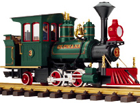
Ok, so this is the locomotive in question, LGB# 22130 - The Waimanalo Olomana Steam Loco #3.
It's a cool little sugar cane train, that we saw pictures of when we were in Hawai'i... so my wife decided we should have one. (demanded is more like it!)
She doesn't know it's coming however, so if you read this before March 24, 2006, don't say anything!
My apologies for the lack of a 'step by step' instructional, but I really got into doing this loco, and as a result, completely forgot to get out the camera, until half-way through. And then, forgot to take more, again, as I finished up.
Overall disassembly isn't too hard.
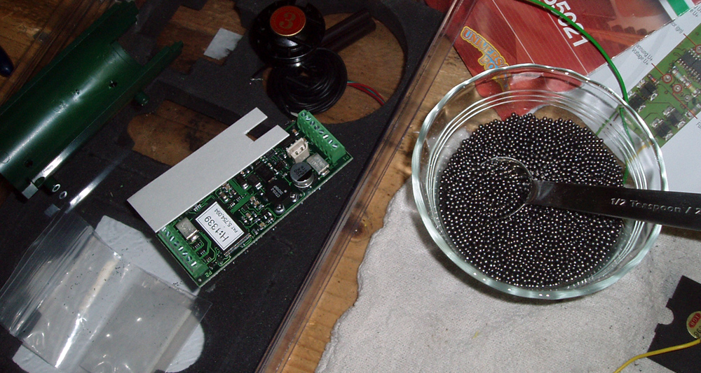
Most screws on this one are obvious, just keep track of where they came from, as there are some different sizes. You should have two larger ones left afterwards, from the lead weight. The front boiler plate, just pops off.
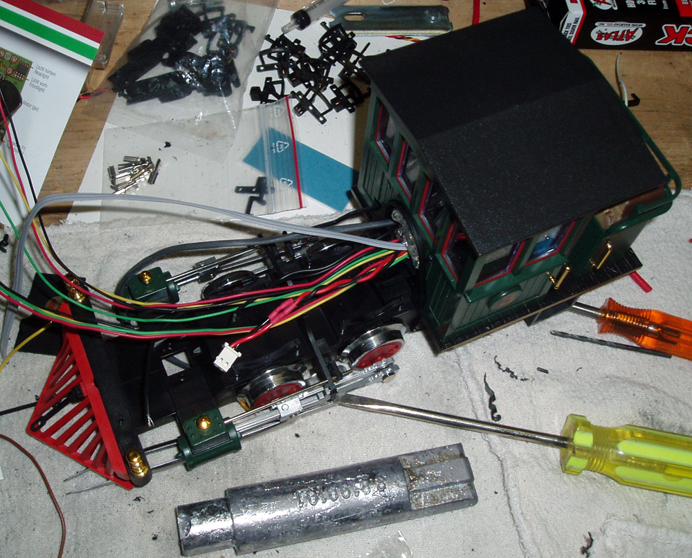
Above, you can see the Phoenix sound card, part of the front boiler (left), and the lead shot I used to try and add some weight.
The problem you will soon see, is that this thing is already too light on the tracks... and we're about to remove the main weight, to make room for electronic parts. So, I bought a bag of #9 buckshot (the smallest I could get), and packed just about every sealed opening I could, with it. In addition, I picked up some sticky-back (peel and stick) tire balancing weights from the local hobby shop. These are hard to find, but they are the lead weights that tire places use to balance expensive alloy rims, where they don't want to bang old fashioned crimp weights onto the rim. So, these are nice, dense lead weights, that are actually coated, to minimize your lead handling. (ask at a tire shop, if you get stuck)
Careful... this is lead. Use tools, wash hands, etc. And it does conduct electricity, so don't let any of it get loose inside anywhere. I painted some of the solid weights black, and stuck them on and under the chassis, to also add weight. (final pictures to come)
A hot-melt glue gun, as always, is your friend. Seems cheap and silly, but allows for quick placement of wires, non-conductive mounting of components, and tends to stick to plastic nicely. Don't use the low-temp ones... they may seem safer, but they just don't adhere nicely. If you ever need to encourage hot-melt glue to come off, douse it with methyl-hydrate, wait a few seconds, and then pull. The methyl-hydrate seems to break the glue bond at the edges, and make it easier to pull off.
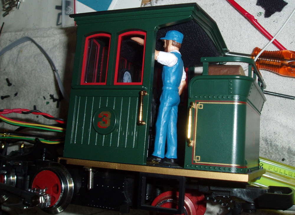
So, here we're looking at the rear wood box. It comes off, two screws on the bottom.
Inside it is where we put the MTS Decoder II, and the battery for the sound card.
Wires for both devices were replaced with longer ones, all joints soldered. Pins were clipped off the decoder, and wires were directly soldered on.
In addition, I soldered the headlight wire, to both forward and reverse terminals, so that it stays on, no matter which direction the loco is going. (there is no back light on this loco)
From there, I bundled the wires in some shrink tubing (seen above, grey in the picture, but disappears as almost the floor colour in real life). Cut a curved notch in the woodbox at the floor, and one in the boilerplate, and passed the wires through to the front, leaving them nice and long, to be trimmed later when actually connecting them.
While doing all of this, I actually had the entire cab off, but as noted, just forgot to take pictures.
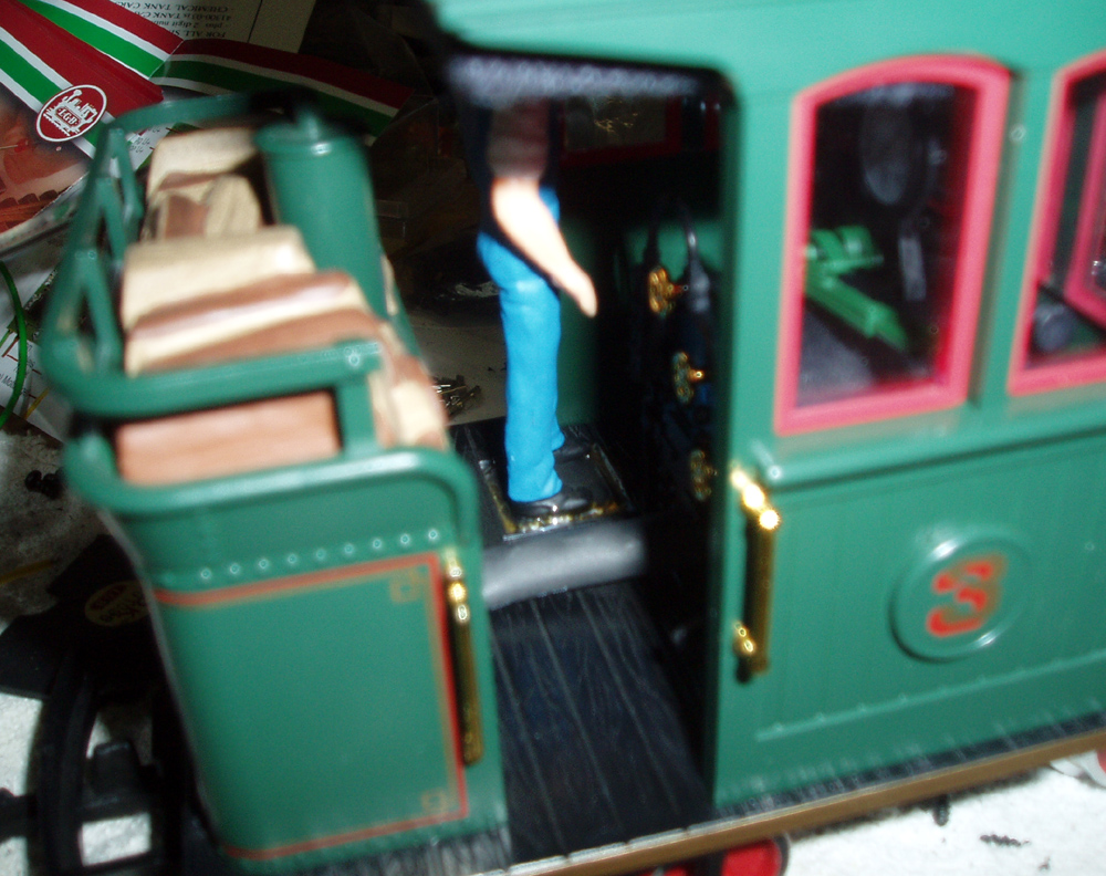
In this picture, you can see the volume lever for the sound card, just under the running board. (another image will show that too) The switch part is inside the cab, and almost impossible to see. The wires just go through a little hole into the boilerplate side again, and forward with the rest.
The sound card computer plug connection, is in the same place, on the opposite side, with the wires run similarly.
More importantly, is the speaker for the sound.
Look back up one picture... do you see the grey fuzzy stuff, just under the roof of the cab? That's the edge of a speaker box, covered in thin black cloth, to make it disappear. (used an old cotton dress sock, stretched) You can see it in the picture just above here, if you look closely. The textured ceiling of the cab...
This is where I wish I had taken more pictures... the speaker in question, is a small PC speaker, that has a particularly small magnet on the back. Dig through your local PC supply house, or electronics warehouse, and compare one to the other... you need one that's the thinnest you can get. The magnet on this one, was maybe 1cm thick.
So, by shaving the roof truss down a bit on the inside, on the side opposite the driver, the speaker clears his head, and fits.
I then -- very important -- build a cardboard enclosure for the speaker to sit in, and seal up the sides. In other words, the thin but stiff cardboard, has a 2" round hole that matches the speaker seat, but on the one side where the speaker hangs down a bit, it closes in a squared box. Coloured it black, and covered it with the stretched black cotton dress sock. I made it a tight fit, but still put a bit of glue to hold it in.
Speaker wires are tiny and black, running down either side of the inside of the cab, in the front corners, down to the boiler plate, and in through tiny drilled holes.
The enclosure for the speaker is important, not to just hide the speaker, but to box it in, gives it the correct setup to breathe properly. A speaker merely sitting in free air, does not work properly, and sounds like crap. Box it, and it can deliver some bass, and has some air to push against.

Here, you can see the volume toggle switch for the sound (bottom) and the plug for the computer connection (top). The position was important, so as not to run into things in the cab. Just have a look at yours, and you'll see what I mean.
The plug for the PC connection cable, is shiny and brass when it arrives, but I took a black sharpie marker to it, just to help disguise it. I suppose you could do the same thing with the silver volume switch as well.
Note the holes/covers in the front area. The first hole has some lead weight in it... I added more.
The next hole has all of the motor connections. This is where you have to remove the small factory DC-only analog board, and prepare to make connections from the decoder. It's all in the instructions. I also ran two fresh wires down here, from the soundboard, to get power for the sound.

Looking at it from the top now, you can see all of the wires coming together. Also note, what I have stuffed that hole in the back, with a little sealed plastic baggie of lead shot. Again, any spot you can find to add some weight again, or else it will have no traction.
Here, we can see the grey flat wire from the volume control, the thick black sheathed wire from the PC communications jack, the extended battery wire (with correct plug back on the end), and the various wires from the decoder, both for the front light, the F1 function, power, and the motor.
The F1 function is an option... but I wanted to run it, as I plan to put a smoker unit in the stack as well!
In the category of weight replacement, you can see that weight I am talking about, right here.
The loco needs to weigh about 1100g when done, to get back to factory weight.
So, on the flat parts under the boiler, I stuck the lead tire balance weights that I mentioned above. (more pictures later) I even need to add some more, as after final assembly I discovered that it was a little rear-heavy.
In the top of the boiler box, I unscrewed the dome and steamcap, and filled them with leadshot too. Then, sealed a small section in the upper half of the boiler, with yet more weights.
Unfortunately, as noted, I got so much into it, I forgot to take any more pictures. If it's apart again, I will.
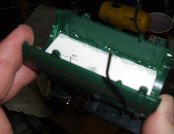
But, here's where we go from there.... the white cardboard you see sealed in, has also had the corners of the inside of that boiler shaved down a bit. (see them?)
The Phoenix sound card, sits right in there, on top of the cardboard, and then the boiler is sandwiched together onto the chassis of the loco.
As you put it together, you attach the wires to their correct terminals, cutting them to the now easily determined lengths.
Once screwed on, and the front boiler/smokestack being the only part missing, I slipped another small plastic bag into the one void in the main boiler, and filled that with lead shot too, and sealed it.
All wires get routed now... two to the front light, two left in the front boiler cover for the smoke upgrade down the road, and the rest straight down through the floor into the motor connection box, where I soldered them on to clips provided, and stuck them on the motor/track-pickup points.
Onto the track it went... and off it went!
The default MTS ID is #3, so I left it... since it is loco #3.
Brought over the laptop, downloaded the correct sound set for this era of loco, and off she went, chuffing and whistling.
Any questions? Feel free to email me. andrew [at] bienhaus [dot] org.
Last Updated: 2015-11-25 11:02:21 AM -0500